
Stihl FS55R Parts Diagram PDF: A Comprehensive Guide
Navigating the intricacies of your Stihl FS55R demands a reliable parts diagram PDF for efficient maintenance and repairs.
Genuine Stihl resources‚ alongside trusted retailers‚
provide detailed schematics‚ ensuring accurate identification of components for your brushcutter’s longevity.
The Stihl FS55R is a popular‚ lightweight gasoline-powered string trimmer‚ celebrated for its user-friendly design and robust performance in tackling various grass and weed-cutting tasks. This model is a favorite among homeowners and landscaping professionals alike‚ offering a balance of power and maneuverability.
Understanding the FS55R’s construction is crucial for effective maintenance and repair‚ and this is where a detailed parts diagram becomes invaluable. Whether you’re addressing routine servicing like spark plug replacement or diagnosing more complex issues within the carburetor or fuel system‚ having a visual guide simplifies the process significantly.
Accessing the correct parts diagram PDF allows for precise component identification‚ ensuring you order the right replacements and avoid costly errors. Genuine Stihl diagrams‚ available through official channels and authorized retailers‚ guarantee accuracy and compatibility‚ maximizing the lifespan and efficiency of your FS55R trimmer.
Understanding Parts Diagrams
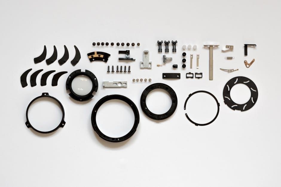
Stihl FS55R parts diagrams aren’t merely illustrations; they are technical blueprints essential for successful repairs and maintenance. These diagrams utilize exploded views‚ showcasing each component’s precise location and relationship to others within the trimmer’s assembly. Each part is typically labeled with a unique reference number‚ corresponding to a detailed parts list.
Successfully interpreting these diagrams requires understanding common conventions. Different line styles often indicate varying levels of assembly or detail. Shaded areas might represent components included in a specific sub-assembly.
When using a parts diagram PDF‚ always cross-reference the reference numbers with the accompanying parts list to confirm the correct component name and part number. This prevents ordering incorrect replacements. Resources like Repair Clinic offer diagrams‚ manuals‚ and videos to aid comprehension‚ ensuring even novice users can confidently navigate the intricacies of the FS55R’s internal structure.

Essential Components & Their Locations
The FS55R’s core functionality relies on key parts – engine‚ fuel‚ and ignition systems – strategically positioned for optimal performance and accessibility‚ as shown in diagrams;

Engine Assembly Breakdown
Dissecting the Stihl FS55R engine assembly requires a detailed parts diagram to understand the interplay of its components. The cylinder‚ piston‚ connecting rod‚ and crankshaft form the engine’s core‚ demanding precise alignment for efficient combustion.
Diagrams clearly illustrate the placement of the cylinder head‚ spark plug‚ and exhaust port‚ crucial for understanding ignition and emission control. Examining the recoil starter assembly‚ including the pawls and spring‚ aids in troubleshooting starting issues.
Furthermore‚ the carburetor mounting flange and intake manifold are vital for fuel delivery. The cooling fan and fins‚ visible in the diagram‚ highlight the engine’s thermal management system. Accessing a PDF parts list allows for accurate identification of each component‚ facilitating effective repairs and maintenance‚ ensuring your FS55R operates reliably.
Fuel System – Carburetor & Tank
The Stihl FS55R’s fuel system‚ detailed in the parts diagram PDF‚ centers around the carburetor and fuel tank. The carburetor meticulously mixes air and fuel for optimal combustion‚ with diagrams showcasing the float‚ jets‚ and throttle valve assembly.
Understanding the fuel tank’s components – including the fuel cap‚ filter‚ and fuel line connections – is vital for preventing fuel-related issues. The diagram illustrates the fuel pump’s role in delivering fuel to the carburetor‚ ensuring consistent engine performance.
Identifying the correct replacement parts‚ like the carburetor gasket or fuel filter‚ becomes straightforward with a visual reference. A clear PDF allows for tracing the fuel flow path‚ aiding in diagnosing problems like flooding or fuel starvation‚ ultimately maintaining the FS55R’s power and reliability.
Ignition System – Spark Plug & Coil
The Stihl FS55R’s ignition system‚ clearly illustrated in the parts diagram PDF‚ is crucial for initiating combustion. The diagram meticulously details the spark plug‚ responsible for creating the spark‚ and the ignition coil‚ which generates the high voltage needed.
Locating components like the spark plug boot‚ ignition module‚ and flywheel is simplified with a visual guide. Understanding the connections and positioning of these parts is essential for troubleshooting starting issues or engine misfires.
Using the PDF‚ identifying the correct spark plug gap and replacement coil ensures optimal engine performance. A detailed diagram aids in diagnosing problems like a weak spark or a faulty coil‚ allowing for efficient repairs and maintaining the FS55R’s reliable operation‚ extending its lifespan considerably.
Detailed Parts List with Diagram References
A comprehensive parts list‚ cross-referenced with the Stihl FS55R diagram PDF‚ simplifies component identification.
Repair Clinic and Stihl’s resources offer detailed breakdowns for easy ordering and maintenance.
Cutting Head & Line Feed System
The Stihl FS55R’s cutting head and line feed system are crucial for efficient trimming‚ and the parts diagram PDF is invaluable for understanding its assembly.
Detailed diagrams illustrate components like the spool‚ line guide‚ bump feed knob‚ and cutting head cover.
Identifying each part within the diagram allows for precise replacement during maintenance or repair.
Common issues‚ such as line breakage or feed malfunctions‚ can be quickly diagnosed by referencing the exploded view.
The PDF highlights the correct orientation and placement of each component‚ ensuring proper functionality.
Furthermore‚ the diagram aids in understanding the interaction between parts‚ like how the bump feed mechanism engages the line.
Accessing these diagrams through Repair Clinic or official Stihl resources provides clarity for both novice and experienced users‚ streamlining the repair process and maximizing the trimmer’s performance.
Drive Shaft & Gearbox Components
The Stihl FS55R’s drive shaft and gearbox are fundamental to transferring engine power to the cutting head‚ and a detailed parts diagram PDF is essential for servicing these components.
These diagrams clearly showcase the drive shaft itself‚ along with the gearbox housing‚ gears‚ bearings‚ and seals.
Utilizing the diagram‚ you can accurately identify each part for replacement during maintenance or repair‚ addressing issues like vibration or power loss.
The exploded views illustrate the correct assembly order and orientation of each component‚ preventing misinstallation.
Accessing these diagrams via resources like Repair Clinic or the official Stihl website allows for a thorough understanding of the system’s mechanics.
This knowledge is invaluable for diagnosing problems and ensuring the longevity of your brushcutter’s drive system‚ ultimately maximizing its operational efficiency.
Handle & Control Lever Assembly
The Stihl FS55R’s handle and control lever assembly‚ crucial for user comfort and operational control‚ benefits greatly from a detailed parts diagram PDF. These diagrams illustrate every component‚ from the handlebar grips and throttle lever to the on/off switch and locking mechanisms.
A clear understanding of this assembly‚ facilitated by the diagram‚ is vital for repairs involving throttle response issues or damaged control levers.
The exploded views demonstrate the precise arrangement of springs‚ cables‚ and levers‚ ensuring correct reassembly after maintenance.
Resources like Repair Clinic and the official Stihl website provide accessible diagrams‚ enabling accurate identification of replacement parts.
Properly maintaining this assembly guarantees safe and efficient operation‚ enhancing user experience and extending the lifespan of your Stihl FS55R brushcutter.
Anti-Vibration System & Mounting
The Stihl FS55R’s anti-vibration system is paramount for operator comfort during prolonged use‚ and a detailed parts diagram PDF is essential for understanding its components. These diagrams showcase the rubber dampers‚ mounting plates‚ and connecting hardware that isolate engine vibrations.
Effective troubleshooting of excessive vibration relies on accurately identifying worn or damaged parts within this system. The diagram allows for precise location of each component‚ simplifying the repair process and ensuring correct replacement.
Accessing diagrams through official Stihl resources or reputable parts retailers like GHS provides clear visual guides. Maintaining a functional anti-vibration system not only enhances user comfort but also protects the engine mounting points from stress‚ prolonging the overall life of your brushcutter.
Accessing the Stihl FS55R Parts Diagram PDF
Locating the correct Stihl FS55R parts diagram PDF is straightforward; explore the official Stihl website or authorized parts retailers like Repair Clinic and GHS.
Official Stihl Website Resources
Stihl’s official website serves as the primary and most reliable source for accessing comprehensive parts diagrams for the FS55R. Navigating their online platform allows users to pinpoint exact schematics tailored to specific model years and serial numbers‚ guaranteeing accuracy during repairs or maintenance.
Typically‚ you’ll need to register for a Stihl account to fully utilize these resources‚ granting access to detailed exploded views and component lists. These diagrams are often interactive‚ allowing you to click on individual parts for identification numbers and availability;
Furthermore‚ Stihl provides downloadable manuals‚ including instruction manuals that often contain simplified parts illustrations. While not as detailed as dedicated parts diagrams‚ these manuals offer a helpful starting point for basic troubleshooting. The official website ensures you are working with genuine Stihl parts information‚ minimizing the risk of compatibility issues and maximizing the lifespan of your FS55R brushcutter.
Third-Party Parts Retailer Diagrams
Numerous online parts retailers specializing in outdoor power equipment offer Stihl FS55R parts diagrams as a customer service. These diagrams often mirror the official Stihl schematics‚ providing a convenient alternative for those seeking quick access or preferring a different interface. Retailers like Repair Clinic and GHS supply detailed visuals alongside part numbers.
However‚ it’s crucial to verify the diagram’s accuracy and ensure it corresponds to your specific FS55R model year. Some retailers may offer generic diagrams or those for similar models‚ leading to potential misidentification of parts. Always cross-reference part numbers with the official Stihl documentation when possible.
These third-party diagrams frequently include direct links to purchase the illustrated parts‚ streamlining the repair process. While convenient‚ prioritize confirming compatibility before ordering to avoid unnecessary returns or delays. Utilizing multiple sources can help validate information and ensure a successful repair.
Troubleshooting Common Issues Using the Diagram
The parts diagram PDF is invaluable for pinpointing faulty components when facing issues like carburetor malfunctions‚ fuel line obstructions‚ or cutting head failures‚ aiding swift repairs.
Identifying Carburetor Problems
Utilizing the Stihl FS55R parts diagram PDF is crucial when diagnosing carburetor issues. The diagram clearly illustrates each component – jets‚ diaphragms‚ fuel intake screens – allowing for precise identification of potentially problematic parts.
Common carburetor faults‚ such as a clogged fuel filter or a deteriorated diaphragm‚ can be easily located within the exploded view. Referencing the diagram alongside a repair manual helps understand the correct assembly and function of each part.
Specifically‚ examine the diagram for the carburetor’s fuel inlet‚ ensuring no debris obstructs the flow. Inspect the jet needles and emulsion tubes for blockages‚ and verify the diaphragm’s integrity for tears or cracks. The PDF simplifies identifying these components and their precise location‚ streamlining the troubleshooting process and minimizing downtime. Accurate part identification‚ guided by the diagram‚ ensures correct replacement and optimal engine performance.
Diagnosing Fuel Line Issues
The Stihl FS55R parts diagram PDF proves invaluable when pinpointing fuel line problems. It provides a detailed visual breakdown of the entire fuel system‚ from the fuel tank to the carburetor‚ showcasing each hose‚ filter‚ and connection point.
Identifying cracks‚ kinks‚ or blockages within the fuel lines becomes significantly easier with the diagram as a reference. The PDF highlights the fuel filter’s location‚ enabling quick inspection for contamination. It also clarifies the routing of the fuel lines‚ ensuring correct installation during reassembly.
Furthermore‚ the diagram assists in locating the fuel pump and its associated components‚ aiding in diagnosing fuel delivery issues. By visually tracing the fuel’s path‚ you can quickly identify potential leak points or obstructions. Utilizing the diagram alongside physical inspection ensures a systematic approach to fuel system troubleshooting‚ leading to efficient repairs and restored engine functionality.
Repairing the Cutting Head Mechanism
The Stihl FS55R parts diagram PDF is crucial for successfully repairing the cutting head mechanism. It meticulously illustrates the assembly‚ detailing every component – from the spool and line to the bump feed knob and guard. This visual guide simplifies disassembly and reassembly‚ minimizing errors.
When addressing line feed issues‚ the diagram clearly shows the internal workings of the spool housing‚ allowing for easy identification of worn or damaged parts. It pinpoints the location of the spring and retaining components‚ essential for proper line advancement.
Moreover‚ the diagram aids in diagnosing problems with the cutting head’s rotation. It highlights the drive shaft connection and bearing assembly‚ enabling targeted inspection for wear or damage. By referencing the PDF‚ you can confidently replace faulty parts and restore the cutting head’s optimal performance‚ ensuring efficient trimming and weed control.
Safety Precautions When Working with Parts
Utilizing the Stihl FS55R parts diagram PDF is only the first step; prioritizing safety during repairs is paramount. Always disconnect the spark plug wire before commencing any work to prevent accidental starting. Wear appropriate personal protective equipment (PPE)‚ including safety glasses‚ gloves‚ and sturdy footwear.
When handling fuel system components‚ work in a well-ventilated area‚ away from open flames or sparks. Properly dispose of any fuel or oil spills‚ adhering to local regulations. Be mindful of sharp edges on engine parts and utilize appropriate tools for disassembly and assembly.
Referencing the diagram helps identify potentially hazardous components‚ but doesn’t replace safe practices. Ensure the brushcutter is stable and secured during repairs. If unsure about any procedure‚ consult a qualified Stihl service technician. Prioritizing these precautions safeguards against injury and ensures a successful repair.
No Responses